Introduction
Risk-based reliability management (RBRM) for oil and gas pipelines is a strategic framework that combines the probability of pipeline failure (such as from corrosion or mechanical damage) with the severity of its consequences. It prioritises inspection, maintenance, and resource allocation on high-risk segments rather than treating the entire pipeline uniformly. The reliability of oil and gas pipelines is ensured through comprehensive integrity management programs combining strict initial design standards, continuous real-time monitoring, proactive corrosion control, and scheduled internal inspections. Reliability of the oil and gas pipelines is vital because it prevents catastrophic environmental disasters, avoids costly operational downtime, ensures worker and public safety, and optimises financial spending on asset integrity.
Reliability management starts from the initial design to procurement, project execution, inspection and testing, real-time monitoring, and repair and replacement. A risk matrix is drawn based on the risk assessment, which is the product of the probability of failure and the impact of the consequences. Risk areas are classified as low, moderate, or high based on the risk matrix. The integrity assessment is based on inspection, monitoring, and testing of the risk-prone areas, and mitigation measures such as repair or replacement are carried out.
The benefits of this risk-based reliability management include cost optimisation, as it focuses resources on the highest-threat areas. Regular monitoring is done in the lower-threat areas. This saves time, money and energy.
Risk Management Strategy in Oil and Gas Pipelines
Risk management strategy in pipeline reliability management is a systematic approach to address threats to pipeline integrity through risk assessment and the development of risk mitigation plans. Risk management strategy is defined in ASME B31.8S-2010: Managing system integrity for gas transmission pipelines and API 1160: Managing system integrity for hazardous liquid pipelines.
The important steps in the risk management strategy in pipeline reliability management are as follows:
- Definition of scope/item scope that can be subjected to failure
- Identification of threats to each piece of equipment that can lead to failure
- Data gathering for each piece of equipment about design, construction, inspection, operation, etc., and review
- Estimation of the probability of failure and consequences of failure for each threat associated with each equipment item
- Risk assessment considering each equipment threat by assigning probability of failure and consequences of failure
- Risk mitigation plan
Pipeline Reliability Plan
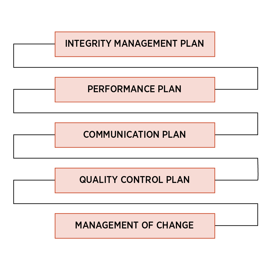
It focuses on the following components:
- Integrity management plan
- Performance plan
- Communication plan
- Quality control plan
- Management of change
The figure below shows these components and the pipeline integrity management plan:
Risk Assessment and Integrity Management Plan
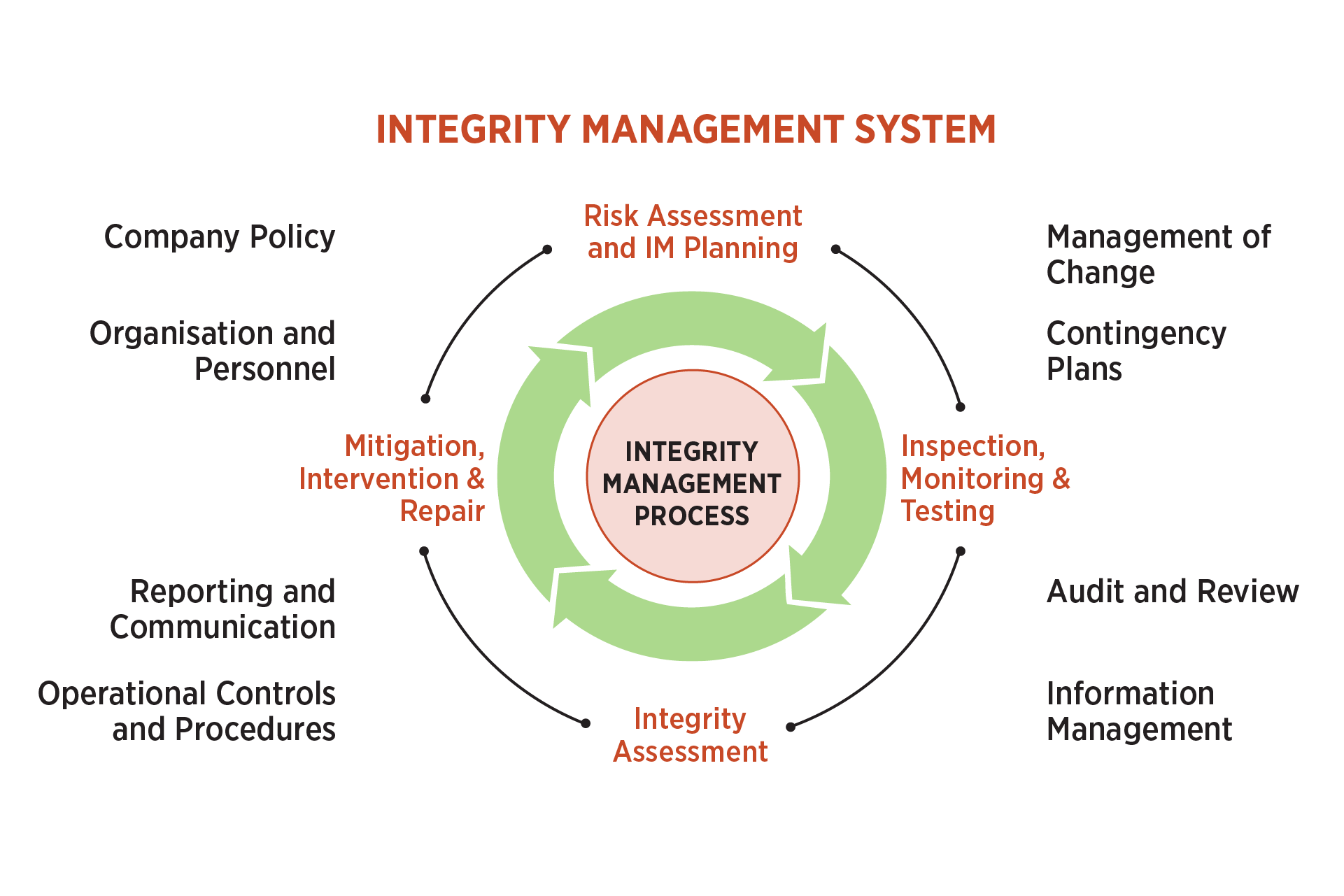
Assets involved in pipeline risk assessment may include pipelines and associated equipment such as valves, safety and control instruments, electrical auxiliaries, SCADA systems, RTU, CP systems, and data and control systems. Each of these equipment items is subjected to multiple threats, and each threat needs risk assessment and integrity management planning.
The figure below shows the process of risk assessment and integrity management planning.
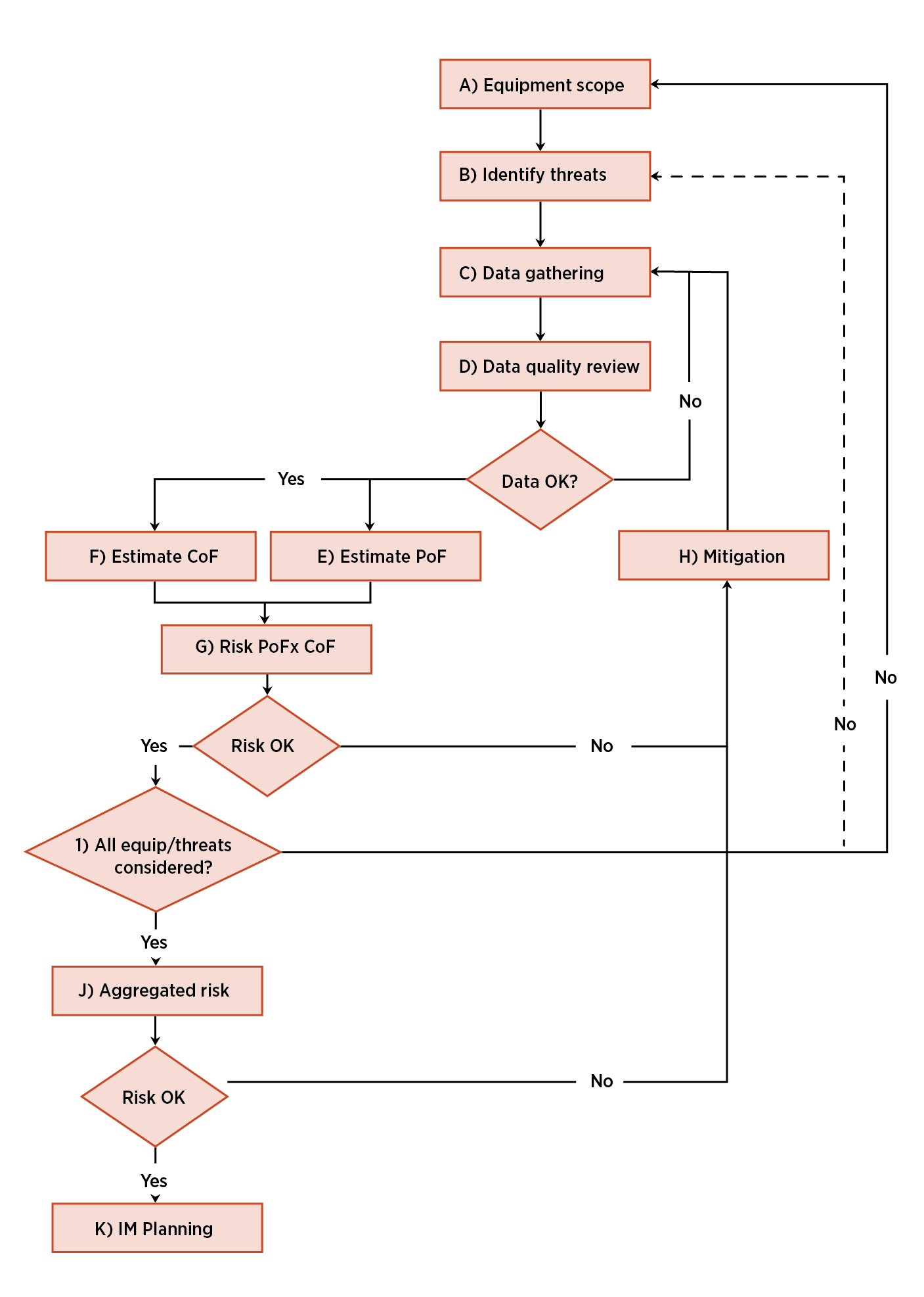
Risk assessment and IM Planning - main tasks and link to code requirements:
- Define equipment/item scope (i.e. all equipment/item that can lead to a failure)
- For each equipment/item, identify all threats which can lead to a failure
- For each threat; estimate risk
- Consequence of failure (CoF)
- Probability of failure (PoF)
- Propose plans for:
- Inspection, monitoring and testing (IMT)
- Mitigation, intervention and repair (MIR)
- Integrity assessment (IA)
1. Identification of Threats
The details below identify the types of threats encountered in an oil and gas pipeline:
- Time-dependent Threats:
- External corrosion
- Internal corrosion
- SCC
- Stable:
- Manufacturing and welding/ fabrication-related defects:
- Defective pipe and pipe seam
- Defective pipe girth weld
- Defective fabrication weld
- Wrinkled bend or buckle
- Equipment:
- Gasket O-ring failure
- Control/relief equipment malfunction
- Seal/pump packing failure
- Miscellaneous
- Fatigue
- Manufacturing and welding/ fabrication-related defects:
- Time-independent Threats:
- Mechanical damage
- Damage inflicted by first, second, or third parties (instantaneous/immediate failure)
- Previously damaged pipe (such as dents and/or gouges) (delayed failure mode)
- Vandalism
- Incorrect operational procedure
- Weather-related and outside forces:
- Cold weather
- Lightning
- Heavy rains or floods
- Earth movements
- Mechanical damage
2. Gathering, Reviewing, & Integrating Data
The tasks after identifying threats to pipeline integrity are to gather, review, and integrate all data related to design, construction, operation and maintenance, inspection, and monitoring. The data and information thus collected are needed to understand the condition of the pipe; identify the location-specific threats to its integrity; and understand the public, environmental, and operational consequences of an incident. The data supporting a risk assessment will vary depending on the threat being assessed. Information on the operation, maintenance, patrolling, design, operating history, and specific failures and concerns that are unique to each system and segment will be needed. Relevant data and information also include those conditions or actions that affect defect growth (e.g., deficiencies in cathodic protection), reduce pipe properties (e.g., field welding), or are related to the introduction of new defects (e.g., excavation work near a pipeline).
3. Risk Assessment Based on Probability of Failures and Consequences of Failures
Once data is gathered, reviewed, and integrated, the risk assessment process identifies the location-specific events and/or conditions that could lead to a pipeline failure. It provides an understanding of the likelihood and consequences of an event. The output of a risk assessment should include the nature and location of the most significant risks to the pipeline. Risk classification identifies low, moderate, and high threat areas that need attention in the form of monitoring, time-bound mitigation, or immediate action.
The objectives of risk assessment are as follows:
- Focus on vulnerable areas (Impact is higher, such as forest area, high population density, green area, etc)
- Readiness for contingency plan (Firefighting apparatus, spares)
- Effective decision-making in selection of inspection and monitoring tools and their schedule
- Allocation of resources in time for effective mitigation measures
- Cost optimisation by selecting appropriate inspection methodology and mitigating measures (efficiency)
- Planning qualified and experienced personnel for interpreting results and improving inspection tools and mitigation measures (Continuous improvement and training)
4. Classification of Safety Class for Determining Impact
Safety class is divided into low, medium or high depending upon classification of fuel (oil or gas), and location (population density). The following table indicates the safety class:
5. Consequences Due to Failure
Potential impact area due to pipeline failure can be calculated by calculating the radius of the impact area
r = 0.69 * d√p
where,
d = Outside diameter of pipeline in inches
p = MAOP of section of pipeline in psig
r = Radius of impact circle in feet, or
r = 0.00315* d√p
where,
d = Outside diameter of pipeline in mm
p = MAOP of section of pipeline in kPa
r = Radius of impact circle in meters
Thus, the radius of impact depends upon the diameter of the pipeline and the MAOP of the segment. The higher the diameter of the pipeline and its MAOP, impact is also higher due to the following:
- Higher population density
- Likelihood of environmental damage such as forest, river or green area
- Increased fire and explosion hazards due to domestic, commercial and industrial areas
6. Risk Calculation
What is risk?
Risk is described as the product of two primary factors: The likelihood of failure or probability of failure, and the consequences or impact of failure.
Risk calculation of threat:
Riskᵢ = Pᵢ * Cᵢ for a single threat
Total Risk for threats 1 to n will be equal to
Total Risk = P₁ * C₁ + P₂ * C₂ +………+ Pn * Cn
Where P is the likelihood of failure, and C is the consequence of failure. Threat categories 1 to 9 are described previously.
Thus, risk for each threat and total risk for all threats are calculated.
7. Assigning Probabilities or Likelihood of Failures and Impact or Consequence of Failures
Assigning probabilities or likelihood of failures:
Assigning impact or consequence of failures:
Risk Matrix:
The above risk matrix shows risk rating based on the product of probability and impact. The matrix can be further shown in numbers as follows:
Integrity Assessment Tools
Once risk assessment is done and risk areas have been identified, the next step is to apply integrity assessment tools based on the criticality of the threats and sections. More than one tool may be required to address all the threats in a pipeline segment. Inspection using any of the integrity assessment tools may not be the appropriate action for certain threats. Integrity assessment tools may include preventive measures such as inspection, monitoring, and testing. The inspection, monitoring and testing tools are tabulated below based on the specific threats.
Mitigation, intervention, and repair:
The results of the integrity assessment will pave the way for deciding on mitigation, intervention and repair. The action may require three actions: monitoring only, planned action, or immediate action, based on the risk of failure, which may be low, moderate, or high. The proposed action depends on the critical pressure, which is the pressure at which the pipe can operate; any pressure beyond this critical pressure will lead to pipeline failure. This critical pressure can be calculated per ASME B31G or DNV-RP-F-101, considering metal loss in depth and length.
The proposed action based on the critical pressure can be summarised as below:
Conclusions
- Risk-based Pipeline reliability or Integrity Management Model is a noble concept for systematic identification of threats to asset integrity and risk assessment analysis.
- Based on the risk assessment analysis, an integrity management plan is conceptualised for inspection, monitoring and testing, integrity assessment, mitigation and repair
- The benefits of PIMS are long life of assets, cost optimisation, brand image and operational efficiency.
References
- ASME B31.8S: Managing system integrity of gas pipeline
- ASME B31G: Manual for determining strength of corroded pipeline
- API Standard 1160: Managing System Integrity for Hazardous Liquid Pipelines
- DNV-RP-F101: Assessment of corroded pipelines
About the Author
J.N. Agrawal, B.Tech (Electrical Engineering) and MBA (Marketing), has 40+ years of experience in Oil & Gas, specialising in Pipeline Integrity, Corrosion Management and Cathodic Protection. A former DGM at GAIL India Ltd, he is now CEO of Corrsol Tech, consultant, coach, and trainer. A CP4/CP Specialist and Fellow of ICorr, UK, he has authored books and presented papers at AMPP and ASME conferences. He received the AMPP India Chapter’s Corrosion Awareness Award in 2023.
Mr. J.N. Agrawal
CEO | Corrsol Tech | India